The Blue View - Chainplate Issues

The typical lifetime of the standing rigging on a sailboat is 10-15 years, while the typical lifetime for the chainplates is 20 years. We replaced the rigging in Colombia about 13 years ago, so it is now due to be redone. The chainplates, however, were never replaced, and are now well past their “use by” date. They are totally fiberglassed into the hull, making a thorough inspection impossible without removing a lot of interior  cabinetry and grinding out large sections of the hull. I routinely inspect the exposed portions, and while they never showed the least sign of internal corrosion or water ingress, I knew we were sailing on borrowed time. crevice corrosion

A few days ago, when I was doing our pre-passage rigging check, I noticed a salty, vinegar-smelling substance coming from the chainplate cover on one of the starboard shrouds – not a good sign. There was no doubt in my mind that it was now time to replace the old chainplates, and since the rigging was nearing the end of its life, I decided to replace it as well. In addition, if we were going to get everything done before our South African visas and the customs permit on the boat expired, we would have to hire the work out instead of doing it ourselves. This was going to be an expensive few weeks.

refit chainplate

Because it was not feasible to remove and replace the old chainplates, my plan was to attach stainless straps to the outside of the hull. Holes would be drilled all the way through the hull and the old chainplates, and the straps attached to the hull using bolts secured on the inside with nuts and washers. I've seen this done on another Liberty 458, as well as several similarly designed boats. If the straps are polished, the bolt heads countersunk flush, and the carpentry done right, the end result is, hopefully, not only be strong, but attractive as well.

Cape Town is a great place to get boat work done. They have an active boat building business, and there are hundreds, if not thousands, of local boats, as well as many more boats passing through, all of which support a number of skilled marine tradesmen. Once the decision was made to replace the chainplates, I wanted the advice of experts to make sure I did it right. I talked with the local marine services expert, who quickly contacted a marine architect (to evaluate and design the chainplates), a rigger (to  replace the standing rig), a stainless steel fabricator (to make the chainplates), a marine carpenter (to modify the cap rail, rub rail and interior cabinetry with minimal damage), and a shipwright (who will be drilling the holes). With all these experts, what could possibly go wrong?

Photos were taken and sent to the marine architect, and the various experts conferred with each other. A few days later, Dave, who owns the marine services company called to say the plans were done and the quote prepared. If I came by and signed off on it, we could get started. I checked the quote and the drawings, and thought the price was quite reasonable. But then I noticed there weren't enough chainplates in the quote – we need eight and there were only six in the quote. Dave thought about it, made a trip down to Nine of Cups, and agreed that the quote was wrong. He said he would get it redone and get back to me.

The next day Dave called again and said the quote was revised. I stopped into his office and looked everything over. The price, as expected, had gone up because of the added chainplates. In South Africa, as well as most of the world outside the U.S., everything is done in metric. I'm used to seeing things in millimeters and centimeters, but I still have to convert a dimension to feet and inches to get a feel for the size. While I was checking the drawings, I saw that they were 350mm long, and mentally estimated that that would be equivalent to about 13-14 inches. This just didn't seem long enough to me, so I asked for a copy of the drawing to take to the boat and make some rough measurements, just to convince myself everything was right. Sure enough, the chainplates were too short. Some of the bolts would have passed through the bulwarks instead of the hull, and two holes in each chainplate would have been drilled right into the deck.

Dave apologized again, and conferred with the marine architect who lengthened the chainplates and reworked the drawings. The new quote was considerably higher, and had yet another problem. The fourth quote appeared correct, but was just about double the first quote - not so reasonable anymore. I signed off on it and the stainless fabricator was given the go-ahead.

carpenter delivers the news

That was Thursday. Friday was a holiday, and on Saturday the carpenter stopped by. I told him about the lengthened straps, and he pointed out yet another problem. The hull has a small step just under the rub rail. It isn't obvious because the rub rail hides it. If the chainplates are lengthened, we will need a spacer behind each chainplate, which may or may not be a problem. Dave will need to check with the marine architect on Monday, and hopefully, the machinist hasn't started on the chainplates in case there is another change needed.

Other than that, everything is going just fine.

The Blue View - Troubleshooting Engine Tachometers

We interrupt our inland travel once again to bring you another Blue View. Believe it or not, some folks prefer boat talk to travel talk. Travel resumes tomorrow.

In the last Blue View, I talked about troubleshooting problems with engine gauges, specifically temperature, oil pressure, and water temperature gauges. In this BV, I'll discuss diagnosing problems with tachometers.

Despite the fact there are different tachometers intended for outboard two stroke and four stroke engines, inboard gasoline and inboard Diesel engines, they all basically work the same - they all convert the number of pulses per second on the input terminal to engine RPMs.

Different types of engines generate these pulses by various methods. Some engines generate the pulses electronically, and there is one pulse per engine revolution. Many inboard Diesel engines use the alternator output as the tach input, and the number of pulses per revolution is a function of the number of alternator poles and the ratio of the alternator pulley size to the engine pulley size. Other engines use a magnetic pickup mounted next to the flywheel and generate one pulse for each gear tooth - in which case, there are two or three hundred pulses for each engine revolution.

Size, shape and color aside, tachometer manufacturers usually have different models available for different engine types. One option is the full scale range. The old Ford Lehman engine on Nine of Cups has a maximum RPM of 2800, and I don't want a tachometer that indicates a red line at 6000 RPMs and a full scale of 7000 - my idle speed of 800 RPMs would barely deflect the needle. Another option is the "pre-calibration" of the tach. Most manufacturers have models calibrated for the more common engines, thus avoiding the necessity, in most cases, of requiring specialized equipment and an hour or two of time to calibrate each tachometer when it is installed.

Okay, enough theory - let's get on to troubleshooting. There are typically four problems that can occur with the tach: it is totally inoperative and always displays zero; the needle is stuck or permanently pegged; the needle is erratic; or the RPMs are consistently off - either low or high. To test the tachometer, you will need a digital multimeter.

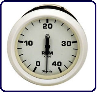
tachometer

Inoperative

Check the obvious - when the ignition is switched on, is there 12vdc (or 24vdc) between the positive terminal and negative terminals when measured with a voltmeter? If not, use your voltmeter to determine whether the problem is in the wiring on the positive side or the ground side.

If the voltage is correct, the next step is to check the input signal. Remove the signal wire. Set your voltmeter to AC volts and connect it between the signal wire and ground. Start the engine and set the speed to idle. You should get a reading on the multimeter that varies with engine speed. If the tachometer is connected to the alternator, this reading should be a minimum of about 5VAC, otherwise it will be more like 0.3VAC. If you get any indication of a pulse stream, reconnect the signal wire, and if the problem is still evident, the culprit is most likely the tachometer itself.

If you get no indication of a pulse stream, disconnect the tachometer signal wire on the engine and repeat the test there. If you detect a pulse stream at that end, the problem must be in the wiring. Otherwise, the problem is in the signal generator.

Needle is Stuck or Pegged

The needle could be stuck in one place or permanently pegged for a couple of reasons. One is that the tach case is tightened down too much and has distorted due to heat or vibration. Try loosening the clamps holding it in place, then tapping the front face piece gently. If the needle frees itself, retighten the tach clamps just enough to hold it in place.

Another possible cause of a stuck needle is over stressing it electrically. This could happen, for example, if the battery cable was disconnected while the engine was running, the tachometer was subjected to large rf noise from a badly tuned or poorly grounded HF radio or from a lightning strike. It is sometimes possible to correct the problem by placing a magnet on the faceplate over the needle and "pulling" the needle free.

Erratic Reading

An erratic reading is usually due to a poor connection somewhere. Start the engine and wiggle each wire leading into the tachometer to try to isolate the culprit. Have someone watch the tachometer while you wiggle the wires on the engine side.

Another possible cause of an erratic reading is electrical noise. Does the problem only occur when the autopilot is running or when sending emails via your HF radio? The problem can sometimes be corrected by putting a resistor in the signal line. It should be placed on the tachometer end of the wire. You may have to experiment with resistor sizes. A 10k ohm, 1/4 watt resistor will often correct the problem without affecting the calibration. If not, try a 1k ohm, 1/4 watt or a 100 ohm, 1/4 watt resistor.

Readings are Consistently Low or High

This is a symptom of the tachometer being out of calibration, which usually doesn't occur unless something is changed. Did you recently replace the tachometer? Alternator? Pulley on the alternator or engine? Some tachometers have multi-position switches or jumpers located on the back or which are accessible through openings on the back. Check that the jumpers are not loose, or if there is a switch, it is possible that the contacts are dirty. Try rotating the switch a few times, then moving it back to its original position.

If necessary, it is usually possible to recalibrate a tachometer. Many older tachometers use switches to set the gross range, and a potentiometer to either fine tune the range or adjust the gain. If the tach is only off by 10%-20% or less, you may be able to recalibrate it using only the potentiometer - otherwise, you will need the manufacturer's documentation to correctly set the switches. Newer tachometers often use a software program for calibration, and you will need a computer, the software and any necessary cabling to calibrate the tachometer.

You will also need a strobe tachometer to determine the engine speed. This is an adjustable strobe light with a digital readout. They used to cost hundreds of dollars, but can now be found online for less than $50. I have also seen apps for smartphones and tablets that simulate a strobe tachometer, and while I can't vouch for the accuracy of these apps, they are probably good enough to calibrate your tachometer to within 5% or so. You can rent, borrow or buy a good one, buy a cheap one or try one of the apps. Then you need to put a mark on the big pulley on the front of the engine. This can be a small piece of tape, a line drawn with a marker, or a dot of paint, just as long as it can be easily seen when you shine a light on it.

Start the engine and increase the engine speed until the engine tachometer displays about half of the engines maximum RPMs. Set the strobe tachometer to the same RPM setting and aim the strobe at the pulley. If the engine tachometer is exactly in calibration, the mark on the pulley will appear to be frozen in place. More likely, the mark will appear to move. If it is slowly drifting around the circumference of the pulley, your tachometer is only slightly out of calibration. If the mark appears randomly all around the circumference of the pulley, your tachometer is very much out of calibration.

Adjust the frequency of the strobe tachometer until the mark on the pulley appears to slow down and eventually stop. The digital display of the strobe tachometer will now be showing the correct engine speed. Adjust the potentiometer on the back of the engine tachometer (or adjust the tachometer using the software) until it reads the same as the strobe tachometer. Check the calibration at 1/4 throttle and 3/4 throttle. In a perfect world, the engine tachometer will now match the strobe tachometer at all three engine speeds. More likely, you will need to adjust the calibration until the error is minimized throughout the engine range.

Now that your engine tachometer problem is figured out, the crew of Nine of Cups is picking up where we left off in the wilds of Swaziland and South Africa. Stay tuned...

The Blue View - Broken Rudder Arm...again

On a passage from Sarasota, Florida to Colon, Panama in 2009, the rudder arm on Nine of Cups broke. The arm connects the hydraulic steering system to the rudder, and without it we can't steer with either the wheel or the autopilot. The original rudder arm was a massive hunk of bronze, and I was amazed that the rudder built up enough force to break it. This occurred about 25 nm out of Colon, and with the heavy ship traffic into and out of the canal, it wasn't a good place to be without maneuverability. We dug out the emergency tiller and hove-to until I was able to jury rig something to get us into port. A few days later, I found a machinist, and I had him make a another rudder arm for Nine of Cups. The new one was considerably beefier than the old one. It was made from a 1” (25mm) thick steel plate, and was held in place on the rudder stock with two 3/8” (10mm) bolts. I thought this would certainly be up to the job, and it did fine for five years.

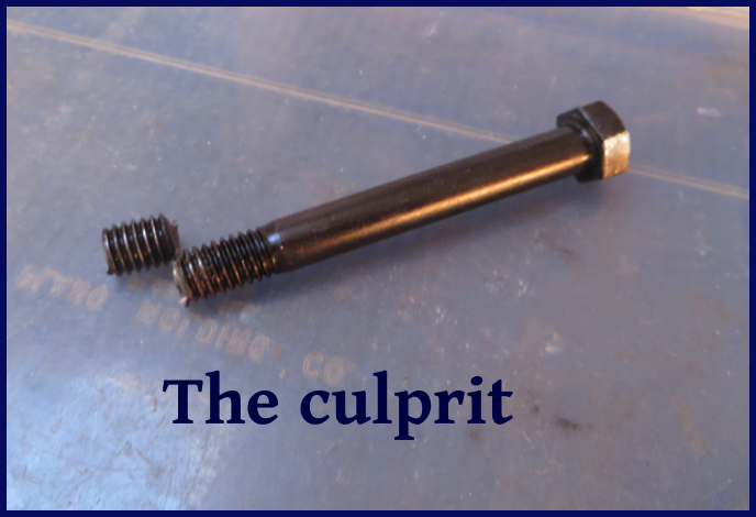
It broke again on the last leg of our Indian Ocean passage from Mauritius to Durban. We had following seas at the time, and apparently the force was sufficient to shear one of the 3/8” bolts in half. I suspect that one of the bolts loosened up, causing a little play between the arm and the rudder. As the waves overtook Cups and hit the rudder, this play would have increased the stress on the bolt.

removing the old arm

If it had to happen at all, we were fortunate that it occurred when it did. The weather was reasonably benign at the time and there were no ships bearing down on us. We were also fortunate in that there was enough remaining of the old bolt to grip it with a pair of pliers and back it out. Once again, we retrieved the emergency tiller and hove-to while I worked on it. It took about half an hour to remove the arm, back the broken bolt out, and secure the arm back in place with a new bolt.

the broken bolt

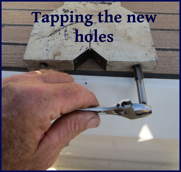
Here in Durban, I increased the bolt size to 1/2” (12.7mm) bolts. The yacht club boatyard next door was kind enough to allow me the use of their drill press, and I was able to drill and the tap the  holes myself. The new bolts have an extra dose of Locktite along with lock washers to keep them tight. I am optimistic this will do the job.

tapping the new holes

It's really good I didn't pick civil engineering as my career choice. If the first two iterations of the bridges I designed all fell down while I worked out the problems, it probably would have been a very short career.

ready to go back in